Every network device starts communicating with other network device after making sure the other device is on and is working fully. But, how a network device can make sure other device is responsive? Network devices check other devices by sending Hello packets. Other devices after receiving Hello packets send Acknowledgement packets. Network devices usually transmit Hello packets after every few seconds.
As we all know, switches are broadcast devices. If every switch starts transmitting Hello Packets, then there will be flood of Hello Packets in the network and original data, that needs to be transmitted will be delayed. In order to avoid this flooding and looping, Spanning Tree Protocol is used in switches. For understanding Spanning Tree Protocol, please have a look at my post.
STP has one Root Bridge per network and this root bridge is known as Mastermind of Network. This root bridge is responsible for keeping network alive for transmitting data. This root bridge initiates sending Hello packets to every switch in the network and receive Response back from every switch to check the status of network. BPDU is a type of Hello Packet used by Spanning Tree Protocol. Bridge Protocol Data Unit is abbreviated as BPDU. By default, Root bridge initiates transmission of BPDU after every 2 seconds. But this can be edited and time can be set as per requirement.
Now, we have understanding of what basically BPDU is. Now, let’s try to understand the structure of BPDU in detail. By structure of BPDU mean, let’s study what’s in the Hello Packet sent by Root Bridge.
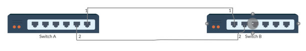
In this diagram, Switch A is connected to Switch B by two ports, Port 1 and port 2. Port 1 of Switch A is connected to Port 1 of Switch B and Port 2 of Switch A is connected to Port 2 of Switch B. Consider Switch A is Root Bridge and it will be responsible for initiating the transmission of BPDU after every 2 seconds. The generic structure of BPDU is:
<Root Bridge ID>/<Cost to the Root>/<Sender Bridge ID>/<Sender Port ID>
Root Bridge ID can be the priority of the Root Bridge or MAC Address of Root Bridge. In our case, we are using MAC Address i.e. Switch A.
Cost to the root is the distance from Sender to root.
Sender Bridge ID is the Priority of Sender Switch or MAC Address of the Sender.
Similarly, Sender Port ID is the priority or Port Number of the Sender’s Port.
Switch A will transmit the BPDU and Switch B. will receive the BPDU. As every port of Switch transmits the BPDU, 2 BPDUs will be transmitted by the Switch A and 2 BPDUs will be received by Switch B. For example, the BPDU transmitted by Switch A Port 1 will be:
A/0/A/1 (Root Bridge ID/Cost/Sender Bridge ID/Sender port ID)
Similarly, for Switch A Port 2:
A/0/A/2
Elections are done on the basis of BPDU. BPDU having smaller Priority/MAC Address or Smaller port Number will be considered as Best BPDU. For example among above two BPDUs, Switch A port 1 BPDU will be considered best because of smaller Port number.
On Receiving end, i.e. Switch B, The BPDUs will be as follows:
Port 1: A/1/A/1
Port 2: A/1/A/2
Among these, BPDU from port 1 will be considered Best BPDU.
In order to avoid loops, Ports sending/receiving worst BPDUs are blocked by STP.
Let’s do another example for better understanding.
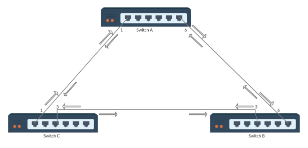
3 Switches: Switch A, Switch B, Switch C
Root Bridge: Switch A
Ports are mentioned in diagram and arrows shows the transmitting and receiving direction of BPDUs on all switches. As this diagram shows and we all know the network is creating a loop. STP will block a port in order to avoid looping and successful transferring of data. Blocking Port depends on Best and Worst BPDUs. Every switch will transmit and receive BPDU. The cost per hop will be 1. The BPDUs will be as follows:
Switch A – Port 1 – Transmit: A/0/A/1
Switch C – Port 1 – Receive: A/1/A/1
Switch C – Port 3 – Transmit: A/1/C/3
Switch B – Port 3 – Receive: A/2/C/3
Switch B – Port 6 – Transmit: A/2/B/6
Switch A – Port 6 – Receive: A/3/B/6
Switch A – Port 6 – Transmit: A/0/A/6
Switch B – Port 6 – Receive: A/1/A/6
Switch B – Port 3 – Transmit: A/1/B/3
Switch C – Port 3 – Receive: A/2/B/3
Switch C – Port 1 – Transmit: A/2/C/1
Switch A – Port 1 – Receive: A/3/C/1
STP will make decisions depending on the above BPDUs received/sent by every Port in the Network.
I hope, now you will have some understanding about what BPDU is and how STP make decisions depending on the BPDU. In order to fully understand the BPDU and how STP makes decisions depending on BPDU, practice different examples. Following are few examples for you to practise.
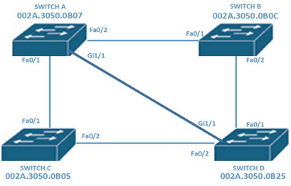
1.
2.
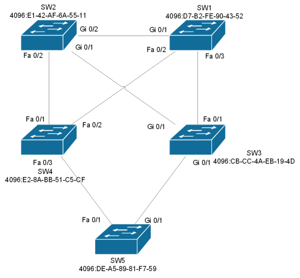
Try to solve these examples and comment your answers. I will check them for you.
I hope this will be helpful for a lot of people who still have any confusion! Please Comment, if you find and confusion or need any help.
Good Luck!
Thanks!

Great info!
LikeLiked by 1 person
Thank you!
LikeLike